1
00:00:03,000 --> 00:00:04,033
Hello,everyone
2
00:00:04,300 --> 00:00:09,233
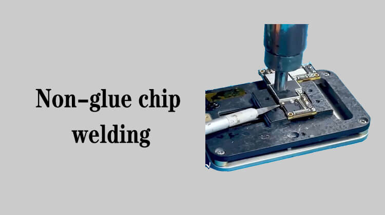
Today, I will show you how to disassemble and solder the chip on the mobile phone motherboard
3
00:00:10,066 --> 00:00:15,033
Some of the chips on the mobile phone motherboard are directly soldered to the motherboard
4
00:00:15,333 --> 00:00:16,333
No processing
5
00:00:16,433 --> 00:00:22,033
After some chips are soldered, some glue will be filled in the gap between the chip and the motherboard
6
00:00:23,333 --> 00:00:26,933
For example, the big CPU chip we are seeing now
7
00:00:28,800 --> 00:00:34,700
The gaps between its peripheral components and the gaps next to the chips will be filled with black glue
8
00:00:36,066 --> 00:00:37,766
We call it glued chip
9
00:00:38,400 --> 00:00:42,566
The other is that no processing is done after soldering to the motherboard
10
00:00:43,633 --> 00:00:48,266
There is no glue in the edge of the chip and the gap of the small component
11
00:00:48,866 --> 00:00:51,900
There is no glue in the gap of the chip,like here
12
00:00:53,200 --> 00:00:54,833
We call it glueless chip
13
00:00:55,433 --> 00:00:59,233
Today we mainly learn how to disassemble this glueless chip
14
00:00:59,866 --> 00:01:01,266
And how to install it
15
00:01:01,766 --> 00:01:05,800
Check the direction of the chip before you are ready to disassemble the chip
16
00:01:06,533 --> 00:01:11,766
For example, the chip you see now is in the direction of the lower right corner
17
00:01:12,100 --> 00:01:14,466
There is a darker triangular arrow
18
00:01:15,666 --> 00:01:23,733
This triangle represents the direction of the A1 pin of the chip, which can also be said to be the direction of the first pin
19
00:01:24,900 --> 00:01:26,933
We commonly call it pin 1
20
00:01:27,466 --> 00:01:34,500
In the case of a drawing, we can disassemble the chip and find this direction according to the annotation on the drawing
21
00:01:34,900 --> 00:01:39,866
There are some Android models or some older ones without drawings
22
00:01:40,233 --> 00:01:44,900
We must make a mark before disassembling the chip about the direction of the pin
23
00:01:45,400 --> 00:01:50,866
Because in subsequent operations, the fixture of the motherboard may change direction
24
00:01:51,466 --> 00:01:54,600
Now we can make a mark at this position in advance
25
00:01:55,266 --> 00:01:58,700
We can use tweezers to make a slight mark on the board
26
00:01:59,466 --> 00:02:02,166
There is a little bit of copper exposed here
27
00:02:02,166 --> 00:02:03,533
Because of the scratch
28
00:02:04,866 --> 00:02:06,533
This is a mark we made
29
00:02:07,133 --> 00:02:13,500
After the chip is disassembled, the first pin must be soldered back in the direction we marked
30
00:02:14,266 --> 00:02:16,066
This is one of the methods
31
00:02:16,066 --> 00:02:20,000
Or use some marker pens or green oil to mark on the motherboard
32
00:02:20,133 --> 00:02:22,466
It is most convenient to use tweezers
33
00:02:23,166 --> 00:02:26,100
This is the preparation before disassembly