1
00:00:03,633 --> 00:00:07,733
In the second disassembly method, we use a grinding pen to grind
2
00:00:08,466 --> 00:00:10,966
Grind the chips directly with this grinding head
3
00:00:12,466 --> 00:00:15,166
But this way of grinding is only suitable for some chips
4
00:00:15,166 --> 00:00:16,366
that can be replaced
5
00:00:19,733 --> 00:00:22,866
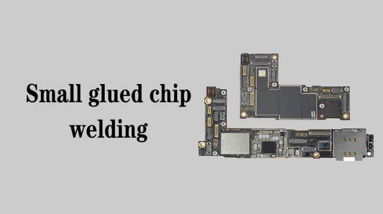
However, like the logic chip and NFC on the mainboard,
6
00:00:24,266 --> 00:00:26,833
they are not suitable for this disassembly method,
7
00:00:27,200 --> 00:00:28,466
because they are irreplaceable chips
8
00:00:32,100 --> 00:00:33,833
If you grind this kind of chips,
9
00:00:33,833 --> 00:00:36,833
then the board basically can't be used as it is
10
00:00:41,200 --> 00:00:44,066
So we can only grind some chips that can be replaced
11
00:00:46,700 --> 00:00:48,800
Now let's see how to disassemble
12
00:00:50,866 --> 00:00:54,366
Use a grinding pen to grind directly on the surface of this chip
13
00:00:55,600 --> 00:01:00,266
Don't press too hard when grinding, just rub it lightly on the surface
14
00:01:03,533 --> 00:01:06,066
Pay attention to the small capacitors around,
15
00:01:06,433 --> 00:01:07,933
try not to touch them
16
00:01:16,100 --> 00:01:18,633
It would be better if the grinding head was smaller.
17
00:01:41,200 --> 00:01:44,200
If there is a lot of debris, we sweep it away,
18
00:01:45,100 --> 00:01:47,233
prevent from blocking our view
19
00:02:45,000 --> 00:02:46,066
sweep it again
20
00:02:46,700 --> 00:02:49,866
Like this area in the middle, we can see the regular little dots
21
00:02:51,800 --> 00:02:55,633
When we see this kind of dot, we don't need to continue grinding down,
22
00:02:57,066 --> 00:02:59,933
because it has been polished to the depth we need
23
00:03:02,066 --> 00:03:04,533
Otherwise, it is easy to damage the mainboard
24
00:03:45,233 --> 00:03:46,466
Change the angle
25
00:04:47,233 --> 00:04:48,666
It's basically done
26
00:04:48,933 --> 00:04:52,433
This position in the upper left corner needs to be grinded again
27
00:05:20,200 --> 00:05:21,966
As well as this corner
28
00:05:24,300 --> 00:05:26,000
All pads should be visible
29
00:05:37,400 --> 00:05:40,300
Ok, now we can basically see all the pads of the chip
30
00:05:40,700 --> 00:05:42,966
which means it has been completed