1
00:00:03,000 --> 00:00:06,333
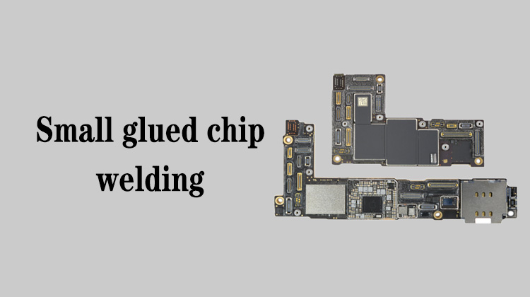
We have completed the chip reballing and pads repairing,
2
00:00:07,800 --> 00:00:09,866
then we will start to install the chip
3
00:00:18,033 --> 00:00:19,600
First, clean the pads
4
00:00:23,066 --> 00:00:26,233
Then blow it with the air gun and add some flux
5
00:00:36,933 --> 00:00:39,300
We don't care if the idle pads break off
6
00:00:39,900 --> 00:00:43,500
This board is very bad and there are lots of idle pads that broke off
7
00:00:43,733 --> 00:00:46,533
When welding, refer to the drawing for pin 1 of the chip,
8
00:00:46,633 --> 00:00:48,933
or refer to the mainboard of the same model
9
00:00:55,266 --> 00:00:59,733
We use a straight air gun to blow the chip back to its original position when welding,
10
00:01:05,166 --> 00:01:09,133
the temperature is 450 degrees, and the air volume is minimum
11
00:01:13,800 --> 00:01:15,133
Ok, it moved
12
00:01:17,733 --> 00:01:19,100
It's already installed
13
00:01:20,833 --> 00:01:22,400
Then we'll install another chip
14
00:01:26,333 --> 00:01:29,100
The mainboard has a certain temperature just after heating,
15
00:01:29,400 --> 00:01:30,933
we don't need to heat it again,
16
00:01:30,933 --> 00:01:33,633
because the PCB conducts heat very quickly
17
00:01:35,633 --> 00:01:38,633
There is a little bit of dirt on the pad, take it off
18
00:01:57,366 --> 00:01:59,666
Do not reverse the direction of the chip
19
00:02:15,166 --> 00:02:19,433
There's a little bit of dirt stuck to the corner, take it off
20
00:02:32,366 --> 00:02:34,733
Let's blow it back with a straight air gun,
21
00:02:37,933 --> 00:02:41,766
the temperature is 450 degrees, and the air volume is minimum
22
00:02:49,766 --> 00:02:54,133
After heating to 450 degrees, we will reduce the air volume
23
00:03:01,600 --> 00:03:03,533
It was reballed medium melt solder,
24
00:03:03,633 --> 00:03:06,200
which melts faster than the surrounding components,
25
00:03:06,566 --> 00:03:09,700
so you don't need to worry about the surrounding tin extrusion
26
00:03:11,966 --> 00:03:13,533
OK, it's back in place
27
00:03:15,133 --> 00:03:17,600
For the tin reballing and pad repairing , you can refer to
28
00:03:17,600 --> 00:03:21,200
the previous videos, I will not demonstrate it here
29
00:03:21,766 --> 00:03:23,233
Then we weld the last chip
30
00:03:25,666 --> 00:03:27,300
First add some flux
31
00:03:33,833 --> 00:03:36,766
Check if there is any dirt stuck on the back of the chip
32
00:03:37,233 --> 00:03:38,200
nothing dirty
33
00:04:13,466 --> 00:04:16,633
Ok, it's obvious that the chip is back in place
34
00:04:19,166 --> 00:04:21,766
In this way, we have already demonstrated the different
35
00:04:21,766 --> 00:04:24,566
disassembly methods of this small glued chip
36
00:04:24,566 --> 00:04:25,933
and the pad processing
37
00:04:27,866 --> 00:04:31,633
When we repair, we need to choose the corresponding chip removal method
38
00:04:31,633 --> 00:04:34,833
according to the different layout of the components on the mainboard


