1
00:00:00,166 --> 00:00:03,000
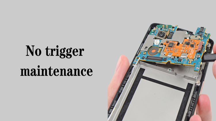
We continue this lesson on no trigger maintenance
2
00:00:03,666 --> 00:00:04,766
As we learned earlier,
3
00:00:05,000 --> 00:00:07,800
if we can't measure the 1.8 volts of the power button,
4
00:00:08,166 --> 00:00:11,166
we have to measure the main power supply that powers the power supply
5
00:00:16,166 --> 00:00:18,133
If the main power supply has no voltage,
6
00:00:18,633 --> 00:00:22,933
the power supply is not capable of outputting the 1.8 volts on the power button
7
00:00:25,800 --> 00:00:26,966
Well, let's take a look,
8
00:00:27,733 --> 00:00:31,733
how do we find the voltage of this main power supply line and where to measure it
9
00:00:35,700 --> 00:00:38,266
We open the PCB bitmap of Xiaomi 10
10
00:00:38,333 --> 00:00:40,333
and the schematic diagram of the mainboard
11
00:00:42,066 --> 00:00:45,900
We know that Xiaomi's main power supply is VPH_PWR
12
00:00:47,400 --> 00:00:50,166
Well, we can easily find it
13
00:00:50,900 --> 00:00:54,833
Right-click in the schematic and click Find Bitmap
14
00:00:55,700 --> 00:00:58,200
At this time, we can measure the main power supply voltage
15
00:00:58,400 --> 00:01:03,466
at these yellow highlighted positions
16
00:01:03,600 --> 00:01:05,733
We click here in the lower left corner,
17
00:01:05,966 --> 00:01:08,366
it will show what is currently highlighted
18
00:01:08,733 --> 00:01:12,433
For example, this is the vph_pwr,
19
00:01:13,533 --> 00:01:17,100
That is to say, in these yellow highlighted positions,
20
00:01:17,366 --> 00:01:19,033
we can test the main power supply
21
00:01:19,400 --> 00:01:21,533
If the main power supply has no voltage,
22
00:01:21,633 --> 00:01:23,300
we need to replace the charging chip
23
00:01:28,733 --> 00:01:30,800
If the main power supply has no voltage,
24
00:01:31,033 --> 00:01:33,833
the power button will not be measured 1.8 volts
25
00:01:37,433 --> 00:01:42,066
There are several reasons why the main power supply cannot measure the voltage of 4 volts
26
00:01:42,333 --> 00:01:44,600
One is whether the charging chip is abnormal,
27
00:01:44,833 --> 00:01:47,800
and the other is whether the battery power supply is normal
28
00:01:48,166 --> 00:01:50,600
Let's take Xiaomi 10 model as an example
29
00:01:50,833 --> 00:01:52,400
Open the circuit diagram
30
00:01:54,333 --> 00:01:57,600
We talked about its conversion main power supply principle earlier,
31
00:01:58,500 --> 00:02:01,366
the chip U5200 is the charging chip
32
00:02:02,633 --> 00:02:06,000
This charging chip is responsible for turning on the positive voltage
33
00:02:06,000 --> 00:02:08,166
of the battery through the internal MOS tube,
34
00:02:08,466 --> 00:02:10,966
and outputting the main power supply from here
35
00:02:18,466 --> 00:02:20,300
Where is the battery voltage measured?
36
00:02:21,033 --> 00:02:24,833
It can be measured on the pins of these capacitors on the battery line
37
00:02:28,066 --> 00:02:30,800
If we want to measure whether the battery voltage is normal,
38
00:02:31,333 --> 00:02:34,866
after buttoning the battery holder, we can measure it here
39
00:02:39,100 --> 00:02:41,100
For example, on this capacitor,
40
00:02:41,433 --> 00:02:44,000
of course, it can also be measured on the charging chip
41
00:02:56,600 --> 00:02:58,466
If we can't measure the voltage here,
42
00:02:59,066 --> 00:03:01,333
but we can measure the battery voltage here
43
00:03:01,700 --> 00:03:05,266
Then we have to re-solder the charging chip U5200
44
00:03:09,400 --> 00:03:12,733
If the main power supply still cannot be measured after re-soldering,
45
00:03:13,333 --> 00:03:15,266
we have to replace the charging chip
46
00:03:20,500 --> 00:03:23,166
When we measure the battery voltage around the charging chip,
47
00:03:23,733 --> 00:03:28,600
if the battery voltage is 4.3-4.4 volts, it is OK
48
00:03:29,566 --> 00:03:31,433
if the voltage cannot be measured,
49
00:03:31,933 --> 00:03:34,166
then we have to replace the charging chip
50
00:03:37,233 --> 00:03:39,300
Okay, that's it for this lesson


