1
00:00:00,400 --> 00:00:02,600
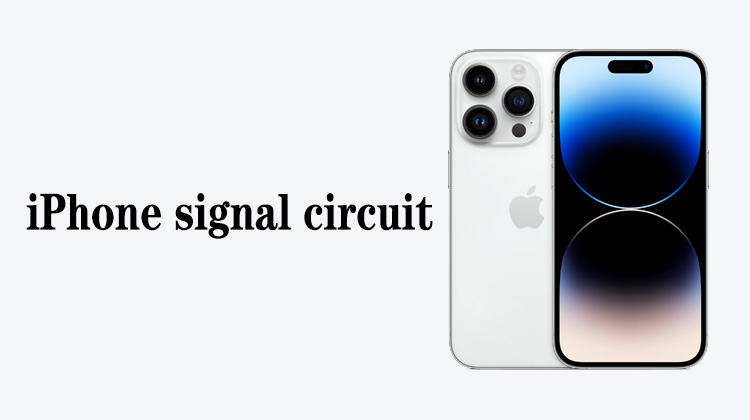
iPhone camera circuit repairing
2
00:00:03,300 --> 00:00:08,933
This video mainly explains the working principle of iPhone 11 Pro, 11 Pro Max front camera circuit
3
00:00:10,966 --> 00:00:14,333
Camera working principle step 1, after starting up,
4
00:00:14,466 --> 00:00:20,500
the main power supply will first output 1.8V power supply to provide the working voltage for the front camera
5
00:00:21,533 --> 00:00:25,033
Step 2, after the CPU working condition is normal,
6
00:00:25,100 --> 00:00:28,133
it will read and detect the front camera through the I2C bus
7
00:00:29,900 --> 00:00:33,233
Step 3, after the CPU detects the camera,
8
00:00:33,366 --> 00:00:36,566
it will send a 12M clock signal for the front camera
9
00:00:37,833 --> 00:00:40,766
Step 4, when starting to the camera circuit,
10
00:00:41,466 --> 00:00:44,100
the camera power supply will control the conversion tube
11
00:00:44,100 --> 00:00:49,233
to provide 2.925V and 1.2V power supply for the front camera
12
00:00:50,900 --> 00:00:53,933
Step 5, when booting to the camera circuit,
13
00:00:54,066 --> 00:00:57,166
the CPU sends an open signal to the front camera
14
00:00:59,000 --> 00:01:04,500
At this time, all the working conditions of the front camera have been met and can work normally
15
00:01:05,200 --> 00:01:13,033
After entering the system, the CPU will turn off the clock signal, open signal, 2.95V and 1.2V power supply,
16
00:01:13,400 --> 00:01:16,633
the advantage of this design is that it can save power
17
00:01:16,933 --> 00:01:19,966
Step 6, when using the camera function,
18
00:01:20,200 --> 00:01:22,400
click the camera icon on the iPhone,
19
00:01:24,300 --> 00:01:26,700
the CPU will control the camera power supply,
20
00:01:26,766 --> 00:01:30,566
and let the camera power supply send the working conditions of the camera
21
00:01:33,166 --> 00:01:38,233
After the camera has working conditions, it starts to collect image information
22
00:01:38,400 --> 00:01:44,266
The camera will send the collected image information to the CPU through the LPDP bus
23
00:01:45,233 --> 00:01:50,600
After the CPU receives the data, it will display the information on the screen
24
00:01:51,566 --> 00:01:57,033
When we click the camera button, the CPU will intercept the current LPDP bus data
25
00:01:57,500 --> 00:02:01,366
and transfer it to the hard disk to complete the camera function
26
00:02:02,066 --> 00:02:04,133
When we click the recording function,
27
00:02:04,433 --> 00:02:08,933
the CPU will continuously transfer the LPDP bus data to the hard disk
28
00:02:09,433 --> 00:02:13,900
When we press stop, the CPU no longer collects LPDP bus data,
29
00:02:14,166 --> 00:02:16,266
and the video recording is completed
30
00:02:17,333 --> 00:02:21,366
In the functional block diagram, SYNC is the synchronization signal
31
00:02:21,366 --> 00:02:23,700
from the front camera to the infrared camera
32
00:02:24,300 --> 00:02:27,533
When we record the face, we can see the picture of the face
33
00:02:27,866 --> 00:02:30,533
This is because when the infrared camera is working,
34
00:02:30,633 --> 00:02:33,500
the front camera will also work at the same time,
35
00:02:33,933 --> 00:02:37,733
so that the imaging information will be displayed on the recording interface
36
00:02:37,966 --> 00:02:40,333
If there is a problem with their sync signal,
37
00:02:40,833 --> 00:02:43,100
or when the front camera is not installed,
38
00:02:43,466 --> 00:02:46,033
there will be no portrait when we record the screen,
39
00:02:46,700 --> 00:02:49,266
but it will not affect the recording of the face
40
00:02:50,033 --> 00:02:55,566
LPDP_AUX is the LPDP bus data detection signal from the CPU to the front camera
41
00:02:57,466 --> 00:02:59,566
When repairing the failure of the camera,
42
00:02:59,800 --> 00:03:02,466
we need to check all the working conditions of the camera
43
00:03:02,733 --> 00:03:07,200
If one of the working conditions is abnormal, the camera cannot be turned on
44
00:03:07,633 --> 00:03:09,366
That's all for this video


